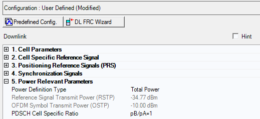
Additional Downlink parameters are described in Cell Parameters (Advanced LTE FDD Downlink), Cell Specific Reference Signal (Advanced LTE FDD Downlink), Positioning Reference Signals (PRS) - (Advanced LTE FDD Downlink), and Synchronization Signals (Advanced LTE FDD Downlink).

Choice: Total Power | RSTP
Default: Total Power
Double-click or use the drop-down menu to select the power definition type.
If Total Power is selected, power reference is Amplitude parameter on Instrument node. In this case, RSTP and OSTP are automatically calculated by Amplitude parameter on Instrument node, Power parameter on Carrier node and each carrier signal settings.
If RSTP is selected, power reference is RSTP. In this case, Amplitude on Instrument node and OSTP are calculated by RSTP, Power parameter on Carrier node and each carrier signal settings.
In multiple carrier case, Power Definition Type parameter in each carrier should be same.
Range: -15.00 to -144.00 dBm
Default: -34.77 dBm
Enter the Reference Signal Transmit Power in dBm, when the Power Definition Type is RSTP. Otherwise displays the Reference Signal Transmit Power in dBm and the value is updated after generation.
Available setting range and step depends on hardware.
See 3GPP TS 36.141 for more information.
Display the Downlink OFDM Symbol Transmit Power in dBm. This parameter is set by the software.
For detailed information about OSTP, refer to 3GPP TS 36.141.
Choice: pB/pA=1 | P_B=0 | P_B=1 | P_B=2 | P_B=3
Default: pB/pA=1
Double-click or use the drop-down menu to select the PDSCH cell specific ratio.